Adding equations to a model
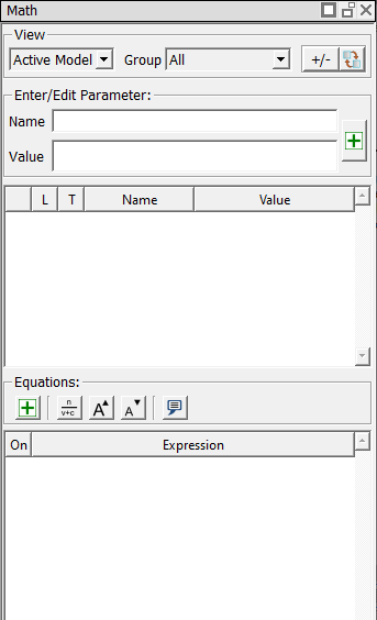
You add equations to your model using the Math view’s equation table. The Concept equation solver solves both geometric and non-geometric equations. As a result, you can add functional properties to your models. You can mix and match dimensions and variables in equations. New variables included in your equations are automatically added to the Math view’s parameter table.
In this lesson, we will use equations to compute the maximum fiber stress (normal stress) in a simple rectangular beam. We will assume that the beam is a simply supported beam with a point load (P) at the center.
In step 1 of this lesson, we will draw the cross section of the beam. In step 2, we will create a new math group to contain our equations, and then add the equations to the model.
Step 1: Draw the beam
- If needed, start a new file by clicking the Create a new model tool from the main toolbar or selecting New from the File menu.
- Using the Rectangle tool
 draw
a small rectangle by clicking two points in the sketch area that define
the upper left and lower right diagonal points of the rectangle. Don't worry about exact values of the dimensions yet.
draw
a small rectangle by clicking two points in the sketch area that define
the upper left and lower right diagonal points of the rectangle. Don't worry about exact values of the dimensions yet.
Observe that the dimensions for the rectangle also appear in the parameter table (the upper portion of the Math view).
Next, we will identify the primary datum surface of the part by placing a fixed point and Line At Angle constraint on one of the lines. We will not place datums in this simple example. For information about datums, see Enventive Concept Help. - Add a Fixed Point and Line At Angle constraint to the rectangle in one step by selecting the Fixed Point constraint tool
 and then clicking on
the right line of the rectangle. The line
at angle constraint is also added to the parameter table, because its
value is modifiable.
and then clicking on
the right line of the rectangle. The line
at angle constraint is also added to the parameter table, because its
value is modifiable.
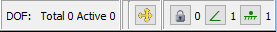
- Observe that the DOF (degrees of freedom) display
in the upper right of the Concept window reads 0, indicating the model
is fully constrained. The display also shows that our model has one Fixed Point and one Line At Angle constraint.
-
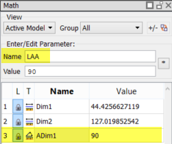
In the Parameter table, click anywhere in the row for the Line At Angle dimension. The name and value are shown in the Enter/Edit Parameter area at the top of the Math View. In the Name field, change the dimension's name to LAA. Press Enter to accept the change.
-
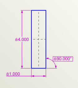
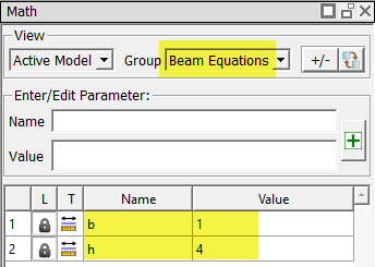
To keep our example simple as we proceed, we will change the dimension values to small whole numbers. Name the width dimension b and change its value to 1. Concept asks if you want to scale the model.
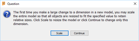
From this message, click Scale. This will also change the height dimension so that its size remains relative to the width dimension.
-
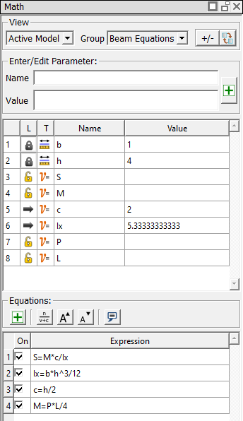
Name the height dimension h and change its value to 4. The Parameter table should now look like the following.
- Right-click in the sketch and select Zoom All from the shortcut menu to resize the display of the drawing. Reposition the dimensions so that your sketch looks similar to the following:
- Save the file as Beam.enb.
You have completed sketching a simple model of a beam. Next, we'll add equations to the model.
Step 2: Add equations to the model
-
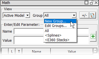
Add a new math group by selecting New Group... from the Group drop-down at the top of the Math view.
-
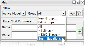
Type Beam Equations as the name of the new group in the New Math Group dialog that opens, and click OK.
The new Beam Equations group is added to the Group drop-down list.
-
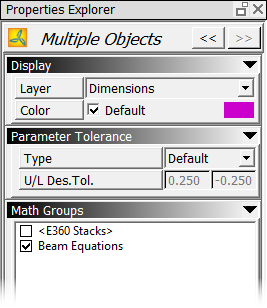
To add the height and width dimensions to the Beam Equations group, extend-select (hold down the Ctrl key while clicking on the dimensions in either the sketch or parameter table) the h and b dimensions, and then select the box next to Beam Equations in the Properties Explorer.
-
Select Beam Equations from the Group drop-down list to make the group active. Note that the Beam Equations group now contains the b and h dimensions.
-
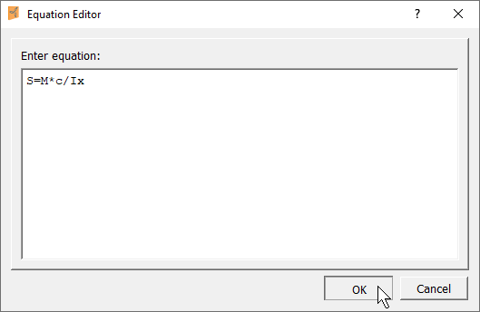
In the equation table (the lower portion of the Math view), click the New Equation button
 to open the Equation Editor dialog, and enter the basic beam
equation for stress (S): S=M*c/Ix. (Recommended: You can copy
each equation from this page and paste it into the Equation Editor.)
to open the Equation Editor dialog, and enter the basic beam
equation for stress (S): S=M*c/Ix. (Recommended: You can copy
each equation from this page and paste it into the Equation Editor.)
-
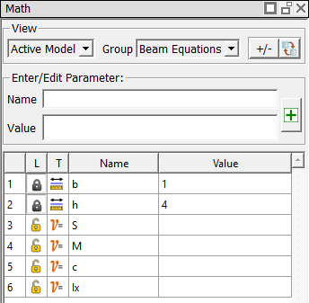
Press Enter or click OK to add the equation. Note that the variables included in the equation have been added to the parameter table.
-
Enter the following equations in the same way you did for the S equation:
- Area moment of Inertia about the x axis (Ix): Ix=b*h^3/12
- Value of distance to the neutral axis (c):c=h/2
-
Moment (M): M=P*L/4
-
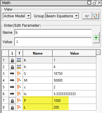
In the parameter table, enter 1000 as the value for load (P) and 200 as the value for beam length (L). Based on the P and L values, Concept computes the moment (M) and stress (S) values.
- Save the file.
After you have entered all the equations, the Beam Equations group will contain the following entries.
You have completed adding equations to the model. In the next lesson, we'll run tolerance analysis on a selected parameter.