Perturbing constraints and non-derived parameters
Constraints and non-derived parameters can be perturbed. Perturbing changes the affected objects and/or parameter values slightly, so you can see the affect the change has on the model's behavior. The effects of perturbation appear in the Sketch view and, for parameters, in the Math view's parameter table. Perturbation has no lasting effect; sketch objects are not modified in any way.
For parameters (variables, dimensions, and line at angle and area constraints), perturbing increases and decreases the value of the parameter. If the value you are perturbing drives other values (see Driving parameter values), you will see the effect perturbing has on those parameter values as well. Perturbation does not actually modify the set value for the parameter. See Changing a parameter value for information about setting values in the parameter table.
To perturb a constraint or parameter:
-
If needed, show constraints in the sketch.
-
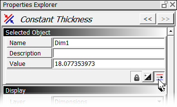
Select the constraint or non-derived parameter you want to perturb. The selected object's properties appear in the Properties Explorer.
-
In the Perturb Control area of the Properties Explorer, enter the desired value in the Max Amount area or use the default value. For some constraints and dimensions perturbation is a linear value; for others it is expressed in degrees.

The Step Size setting for Perturb corresponds with the increments by which the dimension value changes during perturbing. For example, if the Max Amount is set to 1, the dimension value will change by increments of .1 with each movement of the scroll wheel or perturb slider.
-
Click and drag on the Perturb slider to see the effect of perturbation on the selected object.
You may also perturb from within a Solver Warning dialog.
Perturbing Line-to-line dimensions
For Line to Line dimensions, you can perturb either Size or Orientation.

Perturbing Constant Thickness dimensions
For Constant Thickness dimensions, you can perturb the entire length of the constant thickness part or individual elements (individual segments of geometry and dimensions that compose the part).
To perturb the entire length of the constant thickness part, select All as the Element selection option (this is the default).

To perturb individual elements that are part of the Constant Thickness dimension, select the radio button next to the numbers and then select the number of the element to perturb. The numbers correspond to the order in which the elements were selected when creating the dimension.

Note: Selecting the element to perturb has no effect on the dimension display. To move from one element's dimension to the next in the sketch, use the switch position button in the Selected Objects area of the Properties Explorer:
Perturbing a Side-view Floating Pin-In-Hole constraint
The Perturb controls for Side-view Floating Pin-in-Hole constraints have two sliders, labeled X and Y. One slider controls the top point of engagement between the two components, and the other slider controls the bottom point of engagement between the two components.

See the section on creating Side-view Floating Pin-in-Hole constraints for more information.
Perturbing tips
-
If the value being perturbed drives any other values, those values will reflect the perturbation as well.
-
If the model is underconstrained, the results are less predictable, because there are numerous possible solutions.
-
You may need to experiment with the perturb Max Amount value. If results seem meaningless, the perturb value may be too large; try reducing the value to obtain the desired results.
-
Concentric, coincident point, point at midpoint and position constraints have X and Y settings for perturbation. The X perturb control moves the object horizontally (or along the X axis) and the Y perturbation moves the object vertically (or along the Y axis). You can perturb these constraints on only one axis at a time.
-
Collinear constraints have two degrees of freedom; only one may be perturbed at a time.
-
Perturbing a tangency constraint perturbs the underlying point-on-object constraint.