Engineering designers of mechanical products create datums for each component within their geometrical, dimensional, and tolerancing (GD&T) drawings as theoretical references in the form of a point, a line, or a plane from which measurements should be made. Through datums, a designer defines: a) the nominal geometry of a part, and b) the location and orientation of the tolerance zones within which the actual surfaces must lie.
The use of datums, which evolved during and after World War II, are one of the keys to ensuring that assembled parts fit together correctly and that a product will perform to its functional requirements. Datums guide the tooling needed for fabrication of parts and how to measure those parts and their assemblies to ensure that GD&T design specifications are being met.
Datums are especially important in tolerance analysis, which is the process of determining how much variation in size and shape is allowed for each of a product’s individual parts (also often referred to as components). Once all those components are assembled, each of their variances accumulate across the combinations of those components, or what are referred to as stackups.
Tolerance analysis must ensure that these accumulated variations do not adversely impact the functionality of the product. For instance an automotive hinge or latch that is built with excessive variations might not correctly close what it is attached to or it could open unexpectedly.
The best choice of datums for efficient tolerance stackup calculations is to use those surfaces that are positioning the parts within the assembly. The goal is to efficiently define a set of datums that theoretically remove the six modes in which a part can independently move (three linear and three rotational) — in other words to suppress its degrees of freedom.
The representation of datums to support GD&T design decisions are core to tolerance analysis software products, such as Enventive Concept.
This article covers the following datum topics:
- Types of datums
- Datum symbols and representation
- Datum systems and degrees of freedom
- Choosing datums wisely for tolerance analysis
Types of Datums
Point Datums

Point datums are used to specify the theoretical location of a single point, chosen by the designer, either on the component’s external surface, or as the center point of a spherical surface. When used alone, independent of any other types of datums, a point datum suppresses one unique degree of freedom of the component. A single point datum is not enough for locating and orienting the functional surfaces of one or more components and their tolerance zones. To fully remove all degrees of freedom, point datums must be combined with other datum elements.
Line Datums
Line datums specify the theoretical location and orientation of, either an arbitrary line on the external surface of a component, or a centerline of a revolute surface (e.g. cylinder or cone). A single line datum suppresses two degrees of freedom of the component. As with point datums, additional datums are needed to completely remove all possible modes of movement for a component.
Plane Datums
A plane datum represents the theoretical location and orientation of an arbitrary plane of the component’s external surface. By itself, a plane datum takes away three degrees of freedom for a component. You will need to apply additional datum elements to completely remove all six degrees of freedom. Note that a plane datum can be replaced by defining three point datums or one point datum and a line datum.
Datum symbols and representation
Representation of datums on engineering drawings are guided by standards. Enventive finds among users of its software that the two most common standards by far are the GPS (Geometric Product Specifications) standards from ISO (International Standards Organization) or the GD&T standards from the ASME (American Society of Mechanical Engineers).
The illustration below shows a simple example of ISO symbols related to datums and other specifications. The left side shows markup symbols on a drawing of a part while the right side shows the real part with magnified surface imperfections and details what the markups mean to the reader of the drawing. The illustration below as well as the following illustrations are used by permission from Cetim, a France-based research organization that has created an excellent reference handbook on ISO GPS available in English and French. The English version can be downloaded from the top right of this page for free.
A central aspect of ISO, and ASME, standards is what is called a feature control frame (FCF). An FCF visually specifies within a rectangular box the geometric tolerances and datums from which measurements should be made. You can see the FCF above the part drawing on the left with the tolerance value of .1 and reference to datum A. Note that the symbol within this FCF example for a flat plane is per the ISO standard.
Related to the FCF, you can see in blue that a planar datum feature A is identified as the bottom surface of the part with a datum feature indicator — the box with the “A” inside attached to a triangular symbol. The datum feature is the part’s actual, physical surface while the datum is the theoretical surface associated with that feature. You can see this on the right half of the illustration, which shows the part with its real, non-ideal surfaces, at the bottom.
The FCF points to the part’s surface that is to be measured relative to the datum, known as the toleranced feature, and the allowable variation, or tolerance, between the two. In this case the nominal, or Theoretically Exact Dimension (TED), is 25 mm and the positional tolerance zone width has a value of .1 mm, which means that the real surface must be contained between two perfect planes, parallel to datum A at distances of 24.95 mm and 25.05 mm. This is the tolerance zone, which you can see shown on the right

Note that the symbol of a cross combined with a circle used in the above example of FCF for specifying a positional tolerance is used in ISO for both planar and cylindrical surfaces, whereas it is used in ASME only for cylindrical surfaces. Specifying a positional tolerance for a plane in ASME makes use of the surface profile symbol. Also note that the size (width, diameter) of a tolerance zone is ALWAYS specified in linear dimension units, here mm, even when the specification is for orientation ( i.e. with an angular TED value).
To measure an actual part like this one to ensure it is within tolerance, the datum feature surface would be placed on what is called a datum feature simulator, which is a physical surface or device that simulates the conceptual datum. For instance, datum feature A could be placed on a flat table, acting as the datum simulator, from which the distance to the toleranced feature surface can be measured with a micrometer, or other metrology device like a 3d scanner, to ensure it is between 24.95 mm and 25.05 mm. In the case of a cylindrical shaft specified with a line datum, that datum feature simulator might be a lathe chuck in which the shaft is mounted.
To further visualize the relationship between a datum feature and a theoretical datum reference, below is a view of the above illustration in 3D. You can see in blue that datum A is a theoretical plane associated with the shaded surface, the datum feature, which is real surface of the part shown with exaggerated unevenness. The default association rule to apply here is to place the perfect datum A plane as externally tangent to the highest points of the real datum feature. In addition, for the datum feature to be a “good” functional reference, a flatness (i.e. form) specification should be attached to it on the drawing.

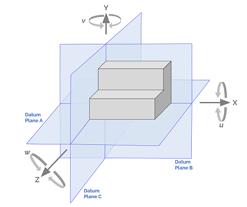
Datum Systems and Degrees of Freedom
A datum system is a collection of two or three datum elements that are based on several separate surfaces chosen with a functional hierarchy giving rise to primary, secondary, and tertiary datums. This collection of datums suppresses all six degrees of freedom of a component when it is assembled into the product. For instance, a primary datum plane will remove three degrees of freedom, while a secondary datum plane or line (e.g. perpendicular to the first ) will remove only two more degrees. A tertiary datum plane, line, or point will remove the last degree.
The illustration below gives an example of a datum system for a block with a cylindrical hole. The FCF shows the system being made up of three datums, A, B, and C, with a tolerance value shown with the circle with a slash through it and 0.1 ( i.e. cylindrical tolerance zone ) for the distance from the centerline of the hole to the B and C datums. You can see in the table that the primary datum, A, a plane on the back surface, removes three degrees by immobilizing the part from moving linearly in the Y axis direction and from rotating in the X and Z axes. The addition of a secondary planar datum, B, on the bottom surface, removes the linear Z and rotational Y movements. The tertiary datum, C, takes away the final movement in the X direction.

It is important in the FCF for this example to list the three datums A, B & C, though the TED distances of 10 and 15 are only from datums B & C — this enforces that the secondary datum B is perpendicular to the primary A, and the tertiary datum C is perpendicular to both A & B. If A is omitted, the perpendicularity conditions to it are lost.
To further visualize these datum system concepts, below is a view of the above illustration showing the part in 3D and with its real, non-ideal surfaces and datums.

The selection of the hierarchy of a datum system is critical to the success of a design. For example, a surface that is especially important to the functionality of a design would typically be associated with a primary planar datum which removes the first three degrees of freedom. This might be a surface that is a relatively large area within the mechanism for which its nominal dimensions and stable positioning are critical. The secondary datum is often a smaller surface that is less critical followed by the tertiary being yet smaller, possibly the smallest.
As part of a system, geometrical tolerance specifications must be applied so that the specific role of each datum surface is correctly achieved. Usually a form specification is imposed to the primary datum surface, and orientation (sometimes position) specifications are applied to the secondary and tertiary surfaces.
Choosing datums wisely for tolerance analysis
While a designers can choose where to place datums in their design as they see fit, choosing datum placements wisely improves the ability to achieve cost-effective designs that robustly deliver on a product’s required functionality. Much of this wisdom comes from experience rather than directly from an understanding of ASME or ISO standards.
For example, by placing datums on contact surfaces that position the product as it is assembled, a designer can minimize the number of contributing component geometries and dimensions to use within a stackup tolerance calculation. Through this kind of datum placement the designer might, for instance, have only five contributors versus, say, ten with a poorly selected placement. In this case this means that the allowable tolerance range for the assembled stack of components can be divided across five contributors instead of ten. Tolerancing values for each of those five contributors can be larger than the ten contributor alternative — possibly two times the values. Larger tolerance values will very likely reduce the costs of manufacturing.


