Drawing and dimensioning tools
Release Notes
This page reflects additions or changes that apply to Enventive Concept v5 and later. We strongly recommend upgrading to the most current version of Concept to take advantage of new features and bug fixes.
Concept v5 expanded Sketch View tools including:
-
New spline creation and spline dimensioning tools
-
New ellipse creation tool
-
New circle creation methods
-
New line creation method
Enventive Concept provides a number of specialized drawing and dimensioning tools to help you with your designing tasks. The drawing and dimensioning tools are visible on the left side of the Sketch view by default.
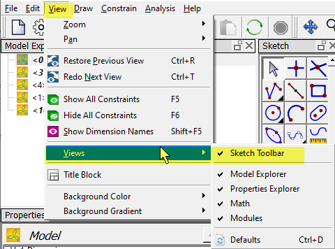
If you cannot see the Sketch toolbar in the Sketch view, make sure Sketch Toolbar is toggled on under the View > Views menu options.
General notes on working with Sketch tools:
-
When you move your cursor over a drawing tool, helpful tooltips tell you how to draw the object.
-
Tools with a black triangle in the lower right corner have multiple modes; for example, tools for creating lines and circles. To select a mode, click and hold or right-click on the tool button, and then select the desired mode.
Drawing tools
The following table describes the geometry, force, and moment tools available in the Sketch view toolbar. You can also use the options from the Draw menu.
For information about trim/extend tools, see Trimming and extending geometry.
For region drawing and constraining tools, see Region tools.
|
Object |
Tool |
Usage |
|
|
The Select tool is the default Sketch view action. When another tool is selected, you can press Esc to return to the Select tool.
|
|
|
|
Click in the sketch area to create a point object. |
|
|
|
Select two objects to insert a point object at their intersection point. This tool may be used to insert points that are needed to trim geometry. |
|
|
|
The Line tool offers two methods for drawing a line. To choose your preferred method, click the line tool and select one of the two options: Line or Line chain.
You can click and drag the line's endpoints (if not constrained) to change the line length/angle. |
|
|
|
Click two locations in the sketch area to define the two endpoints of the centerline object. Enventive Concept automatically adds the centerpoint. You can click and drag the centerline's endpoints (if not constrained) to change the centerline length. The centerpoint is not constrained to remain at the center. The line lengths with respect to the centerpoint may be asymmetric. If one endpoint is stretched, the centerpoint will no longer be at the center. Centerlines have 3 DOF: x and y (translation), controlled by applying constraints to the centerpoint; and rotation, controlled by applying an orientation constraint (line-at-angle, parallel, or perpendicular) or angle dimension to the centerline. The centerpointcannot be constrained to the centerline itself, just as an endpoint cannot be constrained to its own line. |
|
|
|
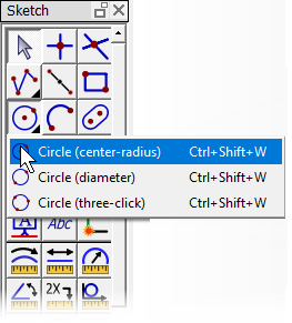
The Circle tool offers three methods for drawing a circle. To choose your preferred method, click the circle tool and select one of the three options: Center radius, Diameter, or Circumferential.
|
|
|
|
Click two locations in the sketch area to define the two endpoints of the arc, then a third location to define the shape of the arc. You can click and drag an endpoint to change the arc size. Arcs are created with centerpoints by default, which can be toggled off. See Drawing arcs for more information about working with arcs and arc centerpoints. |
|
|
|
Click two locations in the sketch area to define the upper left and lower right corners of the rectangle object. |
|
|
|
Click two locations in the sketch area to define the centerpoints of the arcs that form the slot object. |
|
|
|
Click two locations in the sketch area to define the start and end of one axis, and then select a point on the ellipse. |
|
|
|
The Spline tool offers two methods for drawing a spline. To choose your preferred method, click and hold or right-click on the Spline tool and select one of the two options:
For more information, see Drawing a spline. |
|
|
|
On existing geometry, select a corner point to transform the corner into a chamfer. |
|
|
|
On existing geometry, select a corner point to transform the corner into a fillet. |
|
|
|
Click in the Sketch view where you want to insert the text, type the desired text, and click OK. |
|
|
|
Select existing lines/arcs, and press Enter to apply the polycurve to the selected chain of curves. For open polycurves, you can select the first and last line/arc in the desired chain of curves, to select the entire chain. For closed polycurves, you must select each line/arc in the desired chain of curves. |
|
|
|
Draw the force in the same manner as you would a line, by clicking first on the location where you want to begin the force, then clicking again where you want to end the force. Forces appear in your sketch as arrows; the direction in which you draw the force indicates its direction. You may change the force value and direction as desired. |
|
|
|
Click in the sketch where you want to place the moment centerpoint, move the mouse to size the moment as desired, and then click to create the moment. The moment is created in a clockwise direction. |


Dimensioning Tools
To place a dimension on an object, use the Sketch view's dimension tools. Unless otherwise noted, when placing dimensions, first select the dimension tool and then select the appropriate geometric object(s).
|
Dimension |
Tool |
Usage |
|
Spline Auto-Constrain |
|
Select a spline to automatically apply gridded (x,y) dimensions to the spline's control points, resulting in making the spline rigid (0 DOF). For details about creating and working with splines, see Working with splines. |
|
|
Select a line or arc to measure its length. (You can first select the object and then select the Curve length dimension tool if desired.) |
|
|
|
Select two points, a point and a line, or two lines to measure the linear distance between the two. |
|
|
|
|
Select a circle or arc to measure the linear distance along the arc's curve. Switch between radius and diameter in the Properties Explorer. (You can first select the object and then select the Radial dimension tool if desired.) |
|
|
Select two lines between which to measure the angle. Alternatively, to measure the angle of the line to the grid, follow these steps in order: (1) select a line, (2) select the line's endpoint (you may need to use the right-click shortcut menu to select the endpoint), and (3) click in the sketch area at the location to place the dimension callout. |
|
|
|
Select the objects to which the repetitive size dimension will be applied, then press Enter. |
|
|
|
Select a circle or arc, then select a second circle, arc, line or point to measure the distance between the two objects. |
|
|
|
Select a line to use as a grid line. Then, select two points to measure the distance between them, parallel and perpendicular to the selected line. |
|
|
|
Select a force. The X and Y values of the force are added to the sketch and parameter table. |
|
|
|
Select two opposing lines on existing geometry in the sketch. |
|
|
|
Select two opposing lines on existing geometry in the sketch. |
|
|
|
Select geometry to act as the base side, then press Enter to accept the selection; or select a polycurve to act as the base side. Move the cursor to position the ghost image of the offset geometry and click in the Sketch view to place in the desired position. |
|
|
|
Select a set of geometry to mirror and press Enter, then select a line (not part of the initially selected geometry, and usually a centerline) about which to mirror the geometry. |
|
|
|
Select a line, circle, or FOS dimension on which to place the datum. |


